50 A H-bridge and logic board
The off-the-shelf module claimed 43 A and kept burning out whenever a wheel stalled. I led four people building the replacement: a six-layer board with four MOSFETs per leg, current and temperature sensing, and the gate driver's SPI interface converted to CAN.
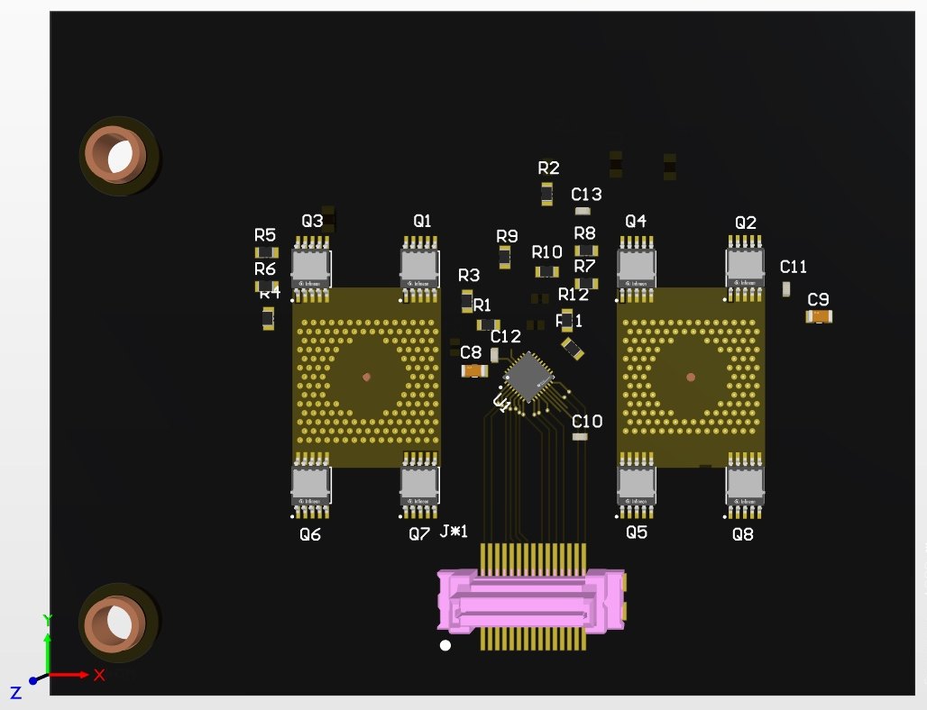
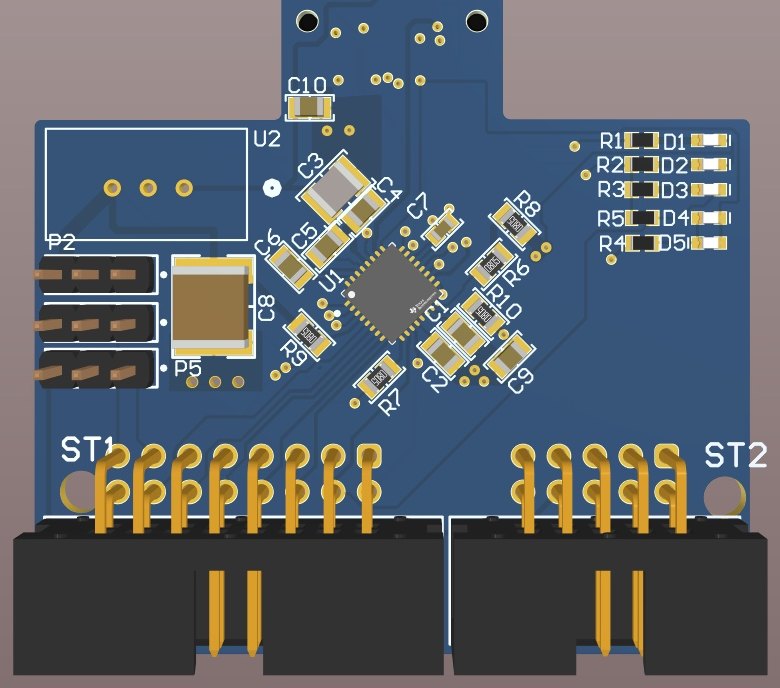
Both images are 3D renders generated from the PCB project, not photographs of the assembled hardware.
- Sheet
- 04 of 06
- Title
- 50 A H-bridge and logic board
- Client
- MORE Vehicle
Autonomous agricultural research vehicle. HAN, client Ad Oomen - Drawn
- Feb 2025 – Jul 2025
- Work done
- Power electronics · PCB design · CAN integration
- Project type
- Group project, 4 people
- My role
- Team Lead, power stage, gate drive, thermal design
- Status
- PARTIALLY VERIFIEDbuilt, bench-tested to 20 A of a 50 A target
43 A on the label, failure at standstill in practice
The existing BTS7960 module advertises a 43 A peak rating. It failed repeatedly under exactly the condition that matters for steering: wheels stationary and on the ground, where friction is highest and the motor draws hardest.
The failure mode was specific, not random: no current chopping, no current sensing, and inadequate thermal protection. The module had no way to detect that it was cooking and no mechanism to back off before it did. A peak rating tells you nothing about sustained stall.
The steering rack is a brushed DC motor with little documentation. It runs on 12 V supply, 40 A fuse. Most of the fleet runs 12 V, one vehicle runs 24 V, and a fully charged 24 V battery reaches about 28 V, which the old module could not handle either. The replacement had to hold up at sustained high current and take the voltage headroom.
Spread the heat, sense everything, split the boards
- Four MOSFETs per leg rather than one large device. Paralleling spreads conduction losses over a much larger thermal dissipation area, and smaller devices switch more efficiently. I selected a part with 40 V VDS for headroom over a 24 V system with transients, 3.3 mΩ RDS(on) at VGS = 10 V to keep conduction losses down, and 23 nC total gate charge for fast switching at the 20–25 kHz used in motor control.
- I chose the older gate driver on purpose. An earlier iteration used the DRV8706-Q1 for its current-sense amplifier and diagnostics. We moved to the DRV8703-Q1 specifically because its higher gate drive, up to 430 mA sink and 230 mA source, reliably drives more MOSFETs in parallel, which is what makes the thermal strategy work. The newer part was the better chip in isolation and the wrong chip for this topology.
- The board is part of the heatsink. Six layers rather than four costs marginal cost, meaningfully better thermal and signal integrity, with dedicated ground and power planes. MOSFETs sit on the back side for power density and direct contact with a heatsink or backplate, and thermal vias and copper pours carry heat out of the devices. M5 terminals rated to 180 A, in pairs, distribute the load.
- Four I²C temperature sensors plus current sensing through the gate driver, so the system can eventually limit allowable current from feedback rather than trip on a fixed threshold. That is the instrumentation the old module did not have.
- Logic split from power across a board-to-board connector: a six-layer power board and a four-layer logic board. Either half can be revised without rebuilding both, and it keeps low-level analogue sensing away from a switching power stage.
- The vehicle runs CAN and the gate driver speaks SPI, so the STM32 bridges them and exposes configuration over CAN. The Bosch steering angle sensor's CAN ID cannot be changed, so the firmware intercepts its frames, reassigns the ID, and combines them with driver telemetry (temperature, current, faults, angle, angle speed) into one message defined in a DBC file.
| High-side MOSFETs | ≈42 °C | at 24 °C ambient |
|---|---|---|
| Low-side MOSFETs | ≈47 °C | hottest devices |
| PCB | ≈47 °C | thermal vias and copper pours |
| Terminals | ≈47 °C | the bottleneck at higher current |
| Gate drive rise | 700 ns | at 10 V, no ringing or shoot-through |
Validated where it was tested, explicit about the rest
| 47 °C | hottest measured point at 20 A for two minutes, 24 °C ambient |
|---|---|
| 700 ns | gate drive rise at 10 V, no ringing or shoot-through detected |
| 6-layer | power board, four MOSFETs per leg, terminals rated to 180 A |
| 20 A of 50 A | bench-validated against the design target |
What passed, passed cleanly. Continuity and power rails checked out, gate drive showed a 700 ns rise at 10 V with no ringing or shoot-through, forward and reverse motor drive worked, and the thermal run at 20 A for two minutes held every measured point at or below 47 °C against 24 °C ambient. That confirms the thermal via and copper pour strategy is adequate at the design currents.
Testing also found the real bottleneck, and it was not the silicon: the M5 power terminals run hot at elevated current, partly from contact resistance introduced by using alligator clips on the bench. A proper test bench with crimped connections is the first recommendation for whoever picks this up.
I will not claim the 50 A target as met. The boards arrived late, extended testing did not happen, and the report says early results indicate it should reach 50 A, which is not the same as saying it does.
Book a call
Happy to talk about a graduation internship, a vacancy, or a project you want a second opinion on. Twenty minutes is usually enough to work out whether it is worth a longer conversation.
- Typical length
- 20 to 30 minutes
- Time zone
- Central European Time, Arnhem
- Languages
- English, Hindi
- Usually free
- Weekday evenings and most of the weekend
Looking for a graduation internship from February 2027.
Power electronics, embedded hardware, renewable energy or power systems. I am equally happy writing the firmware and tooling around them. Based in Arnhem, open to relocating in the Netherlands.
- Phone
- +31 6 8515 8402
- linkedin.com/in/tanishq-bhaiji
- Based in
- Arnhem, Netherlands
- Available
- Graduation internship from Feb 2027